Purchase installation services for a high-pressure roller ball press machine
Time:Aug 21,2023
Our service officially begins from the day the customer purchases the product. After mutual communication and negotiation, we’ll finalize and sign a detailed on-site planning proposal. Following the agreed timeline and specific requirements, Hongxin Mining will dispatch its technical team to carry out the implementation. Based on the equipment layout dimensions and site plans provided by the customer, as well as the exact scope of planning needed, Hongxin Mining will swiftly deliver to the customer an on-site "layout diagram" and "equipment foundation drawings." These documents will then be sent back to the customer via fax or mail for confirmation. Once everything is verified as accurate, construction will proceed according to the provided blueprints.
Installation and Adjustment
1. Installation
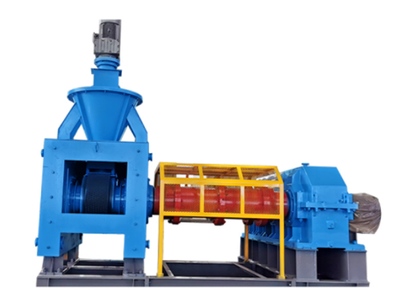
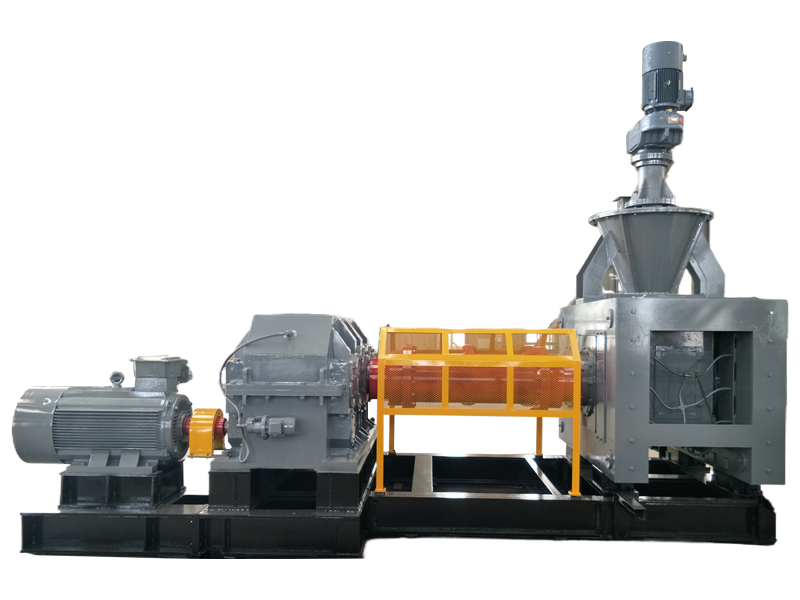
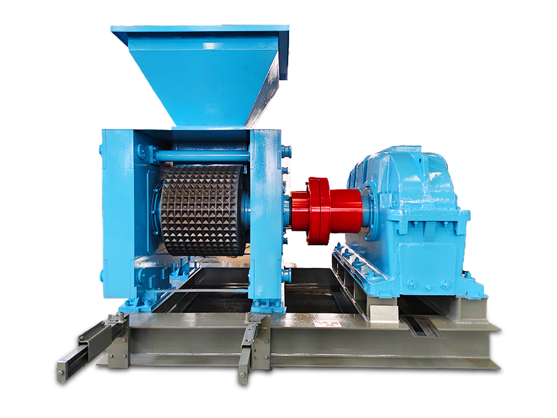
When the ball press machine leaves the factory, it mainly includes the following components:
1) Pressing machine body. The main unit includes the body, hydraulic components, and is equipped at the top with a motor and a turbine gearbox. If the height exceeds transportation limits during transit, the pre-pressing mechanism and turbine gearbox can be disassembled separately.
2) One main reducer unit, with a pulley mounted on the input shaft and one coupling installed on the output shaft.
3) One main motor equipped with one pulley.
4) One ball-pressing machine control cabinet and one speedometer.
5) One vibrating screener (including vibration motor).
6) Attachments: Dowel pins, V-belts, etc.
After the user places an order, follow the instructions in the machine’s manual and carefully construct the foundation according to the user’s own custom configuration diagram (ensure the relative elevations between each component of the ball press machine align with the specifications provided in this manual). Additionally, leave anchor bolt holes in the foundation—refer to the manual for the exact installation dimensions of these anchor bolt holes.
After the ball press machine arrives at the factory, installation should primarily focus on aligning the machine itself. Begin by roughly checking and adjusting its elevation and level, then securely fasten the anchor bolts. Next, use the main reducer as a reference to precisely fine-tune the elevation and horizontal alignment, ensuring the anchor bolts are properly in place. Note that the main motor and the main reducer are connected via V-belts, so you only need to ensure that the motor shaft and the reducer input shaft remain aligned horizontally—adjusting the distance between them according to the belt tension. Once these steps are complete, proceed with secondary grouting to firmly secure the anchor bolts. Minor elevation discrepancies during installation can be corrected using shims. After completing the final adjustments, apply a cement screed over the base surface—but make sure this step is carried out only after all anchor bolts have been fully tightened. Finally, assemble the remaining components according to the overall layout drawing.
2. Adjust
This unit has been adjusted before leaving the factory, but further adjustments may still be necessary due to issues arising from on-site maintenance or operational use.
1. Adjusting the Production Gap of the Press Roll: During production, there are times when it’s necessary to increase output or enlarge the bite angle. In such cases, you can widen the gap between the two press rolls by inserting a 0.1–1 mm-thick shim between the active and passive bearing housings. The steps are as follows: Stop the machine, relieve pressure from the oil pump, move the adjustable passive bearing housing toward the cylinder side, and then insert evenly thick shims at both ends.
2. Adjustment of Ball-and-Socket Alignment The ball-and-socket joint is formed by the mating of concave recesses on the surfaces of the primary and secondary rollers, resulting in both axial and circumferential alignment issues.
A. Axial alignment is pre-adjusted during installation and, generally speaking, requires minimal adjustment. If adjustment becomes necessary, simply tighten or loosen the bolts on the bearing housing to achieve the desired axial alignment.
B. The circumferential alignment steps are as follows: First, loosen the four bolts on the shaft head plate. Next, remove the 11 M20 connecting screws from the adjustment sleeve. Finally, adjust the M20 x 70 bolt on the adjusting pin to achieve the desired circumferential alignment. If the adjustment remains difficult, gently rotate the pulley on the main gearbox back and forth by hand. Since the initial setup already accounts for an adjustable clearance equivalent to a ball socket, any misalignment—no matter how significant—can be easily corrected.
Previous page
We provide professional briquetting machine equipment and competitive quotes.
We will contact you within 24 hours of receiving your message.
Tel:+86-13703990669
Tel:+86-18182214485
Email:sales@hongxinmining.com
Address: Longgang Development Zone, Xingyang City, Zhengzhou City, Henan Province

Email:zzhxjixie@126.com
Tel:+86-13703990669
Tel:+86-371-64696918
Address: Longgang Development Zone, Xingyang City, Zhengzhou City, Henan Province
Leave a Message
The need for specialized plant growth regulators


